4193sn Wiring Diagram
There are three wires present inside the alarm—one is black, one is white and the third is red (or sometimes yellow). Some models might also have a green grounding wire. The line voltage is brought in through the 14/2 Romex coming from the main panel or a terminal box close by.
[DIAGRAM] Fire Alarm Class A Wiring Diagram
586 401K views 11 years ago Typical household smoke alarms use a black wire for detecting smoke, a white wire as the common conductor and a red wire that communicates with other smoke.

Download Notifier Smoke Detector Wiring Diagram Pictures halfdeadbipandaa
Electrical parts and materials for smoke detector wiring projects should be approved for the specific project and compliant with local and national electrical codes. Electrical Codes and Inspections: Installing additional electrical wiring for smoke detectors should be done according to local and national electrical codes with a permit and be.

Est Smoke Detector Wiring Diagram First Wiring
More often, though, hardwired smoke detectors are installed by splicing into a general lighting circuit or outlet circuit. Either a 15-amp circuit (wired with 14-gauge wire) or a 20-amp circuit (wired with 12-gauge cable) is acceptable for powering hardwired smoke detectors. Wiring the smoke detectors is fairly straightforward for an.

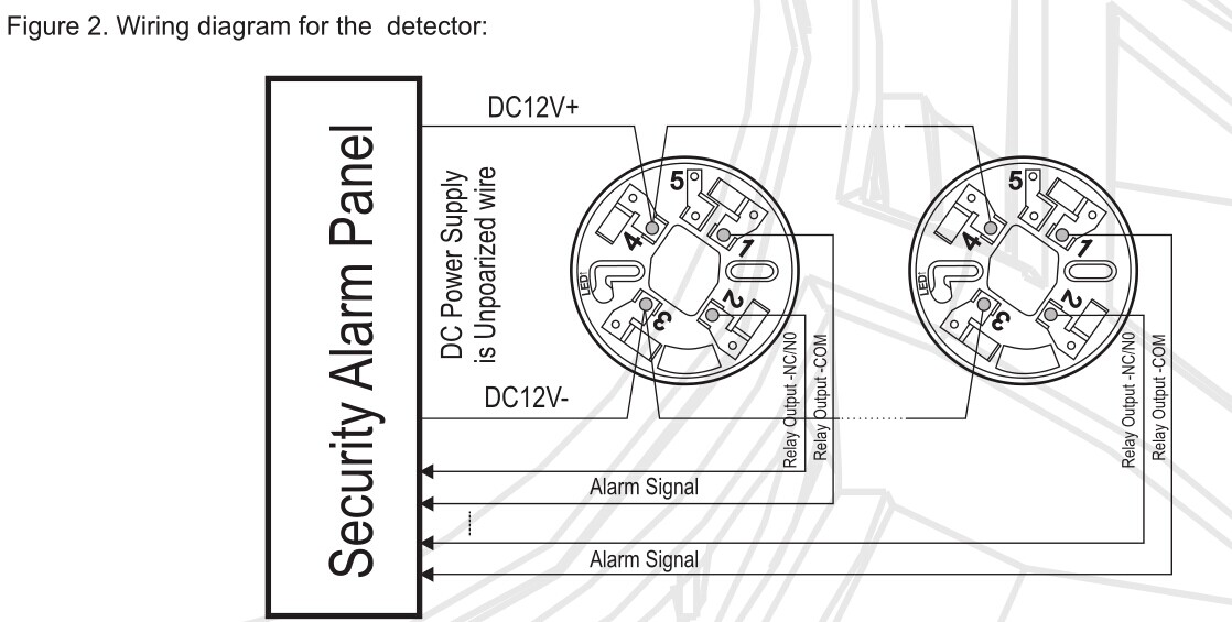
2wire smoke detector wiring diagram
What is the red wire used for on smoke detector? What is interconnect? Why do I only have 2 wires connecting? What do do with the 3rd wire on smoke detector?.

Wiring Diagram For Smoke Detector Wiring Diagram Schemas
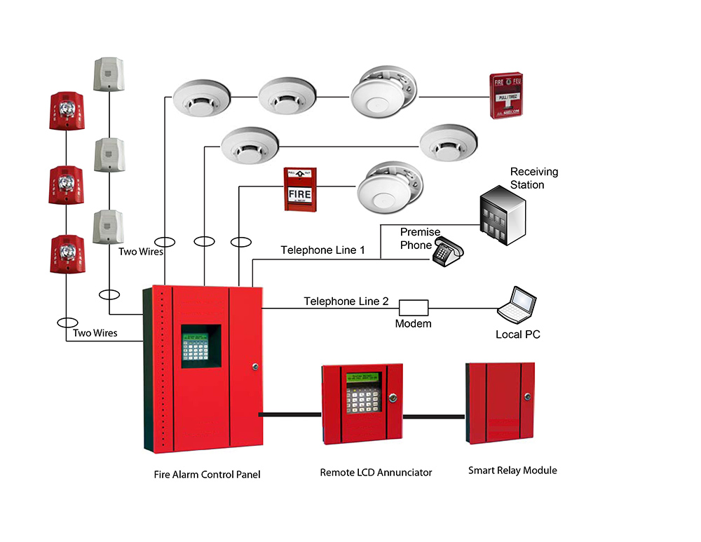
Fire alarm system is the combination of different components such as smoke detector, heat detector, carbon monoxide detector, multi sensor detector, call points, sounders, bells, relay module, repeater, annunciator, fire control panel and other related and optional security devices designed for fire alarm control system.

View Smoke Detector Wiring Diagram Pdf Gif Best Diagram Images
8. Connect the Smoke Detectors. Use wire nuts or the other UL-approved wire connectors to connect the wire leads on the smoke detector on the first box: Join the black circuit wire(s) to the black wire lead on the smoke detector. Connect the white wire(s) with the white wire lead on the smoke detector. Connect all the bare copper wires together.

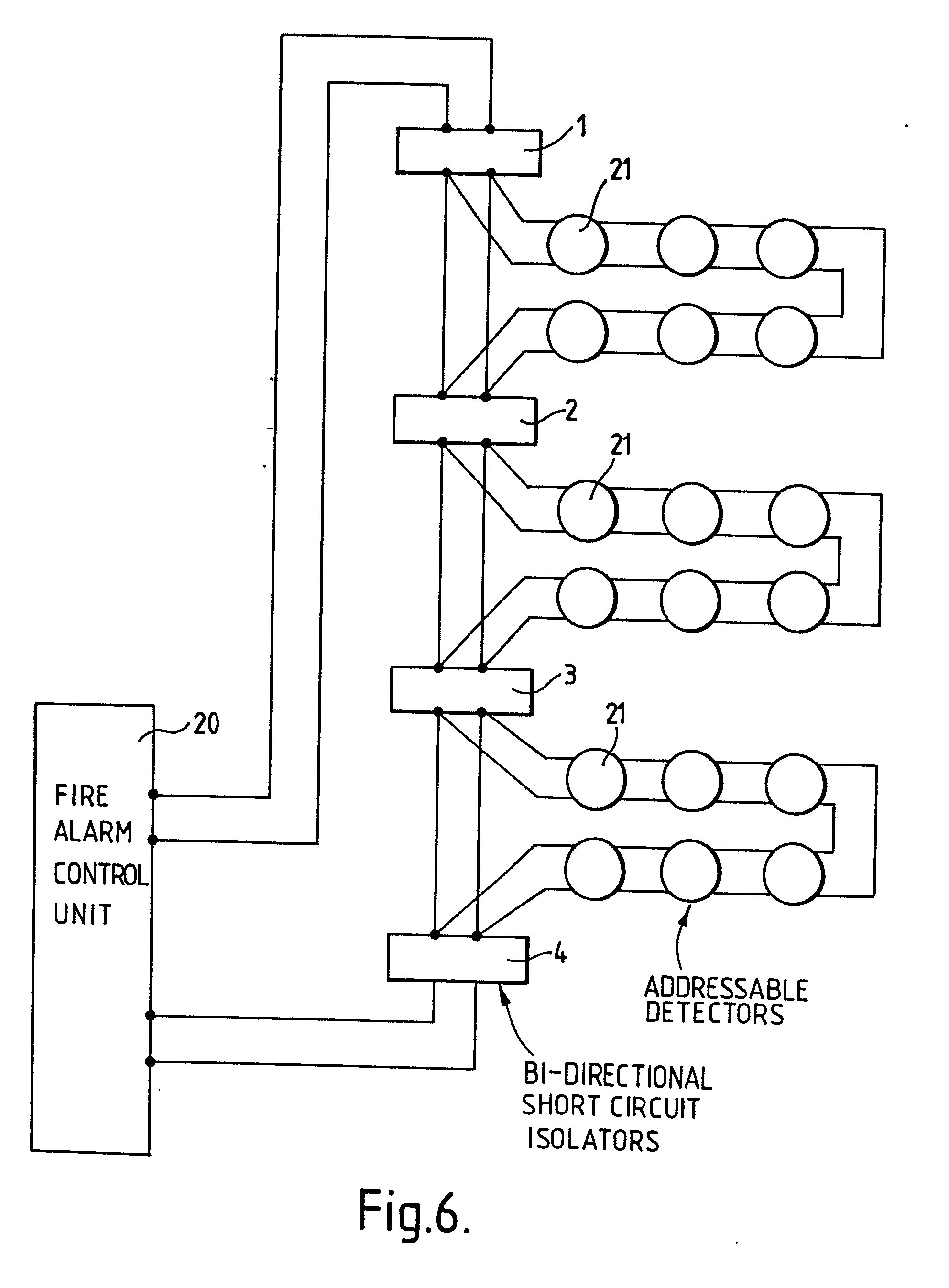
Single Line Addressable Fire Alarm System Wiring Diagram / Fire Detection And Alarm System
Beginner Duration Under 2 hours Smoke detectors should be installed on every level of your home. Make sure to put them in the basement, the attic and include one in each bedroom. Use this guide to find out about different types of smoke alarms. Learn how how to install and wire a smoke detector, too.

Class B Fire Alarm Wiring Diagram Free Wiring Diagram
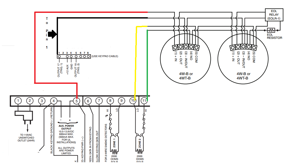
2-WIRE I3 DETECTOR WIRED IN STYLE D CONFIGURATION: CAUTION Any 2-wire i3 smoke detector (2W-B, 2WT-B, 2WTA-B, or 2WTR-B) wired in the Style D initiating device circuit (IDC) configuration requires the use of a 2W-MOD2 module. This is because fire alarm control panels vary by manufacturer on the implementation of Style D circuits. Therefore, the.

Cooper Wiring Devices Pdf inspireado
#1 I have a couple old smoke detectors that are AC powered with battery backup. I replace smoke detectors every 5 to 7 years. The ones I have in place now are rated for 10 years - that's not the concern. As I said, these are older units and may still work. Thinking about using them in the detached garage.
Fire Alarm Wiring Diagram Schematic
12-3 NMB and ground wire. Simple steps to smoke detector battery replacement. Connecting wires. Understandably, the main difference between a wired smoke detector and a battery-powered smoke detector is that a wired detector connects directly to wires in your walls.
Alarm Panel Service And Schematics Diagrams
A 3-wire smoke detector wiring diagram is a diagram that shows the wiring between a smoke detector and the power source. It includes the wiring for the power source, the wiring for the smoke detector, and the wiring for the alarm system.

3 Wire Smoke Detector Wiring
Mount smoke detectors at least 4 inches from wall or on the wall with the top of the detector within 4 inches and 12 inches of the highest point of the ceiling. In multi-story units there shall be a detector at each level and shall be placed at the center of the ceiling 24 inches or more higher than the hall are required to have a smoke.

2Wire Fire Alarm Wiring Diagram First Wiring
Step 1: Turn Off the Power Determine which existing circuit the smoke detectors will be wired into and turn off the power supply to that circuit. Safety first! Keep in mind that any wiring tasks should be done by an electrician, as there is always a risk of shock or electrocution when carrying out this type of work. Step 2: Cut the Holes

Wiring Diagram For Fire Alarms
They also illustrate the wiring connections to other devices, such as fire alarm control panels or relay modules. Installing hard wired smoke detectors involves connecting the hot wire from the electrical circuit to the black wire of the smoke detector, the neutral wire to the white wire, and the interconnect wire to the orange wire (if required).
4 Wire Smoke Detector Wiring Diagram General Wiring Diagram
120VAC power is provided by the hot (black) and neutral (white) wires. Interconnect alarm signaling is carried by the red wire. If one alarm is triggered, it will signal the other alarms to sound. The neutral (bare copper) wire is not used by the smoke alarms and no connection is required.